 `
`
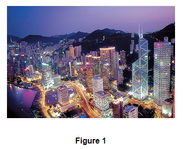
Electricity is an important source of energy in the modern times. Electricity is used in our homes, in industry and in transport. For example, electricity is used in our homes for lighting, For operating fans and heating purposes (see Figure 1). In industry, electricity is used to run various types of machines, and in the transport sector electricity is being used to pull electric trains. Physical phenomena associated with the presence and flow of electric charge is known as electricity. Electricity and electrical phenomena have a lot of applications in our day to day life and they also give a wide variety of well-known effects. It is a controllable and convenient form of energy for a variety of uses in homes, schools, hospitals, industries and so on. What constitutes electricity? How does it flow in an electric circuit? What are the factors that control or regulate the current through an electric circuit? Here, we will get answer of these all questions and we will discuss electric potential, electric current, electric power and heating effect of electric current.
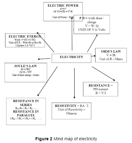
Electricity can be classified into two parts:
1. Static electricity
2. Current electricity
Static Electricity: Static electricity is a type of electricity when electric charges develop but do not flow.
For example charges developed by glass rod are rubbed with silk.
Current Electricity: Current electricity is a type of electricity when the electronic charges that develop are also in motion.
For example electricity used in our homes.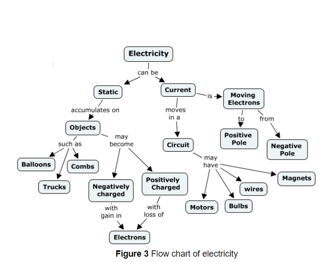
Fractional electricity
To understand electricity we need to understand the concept of electric charge first. Let us understand this concept using this example.
When two dry substances of different types are rubbed together and are then separated , each substance acquires the property of attracting light pieces of paper , dry leaves, straw etc. The substances being rubbed acquire something which gives them this property. That something is called Fractional Electricity. The substances are said to have become charged after acquiring or loosing electric charge.
The fractional electricity produced has been found to be of two types i.e., positive electricity (charge) and negative electricity (charge). The two substances rubbed together acquire equal and opposite charges.
If we bring a plastic comb near some very tiny pieces of paper, it will not have any effect on them. If, however, the comb is first rubbed with dry hair and then brought near the tiny pieces of paper, we find that the comb now attracts the pieces of paper towards itself (shown in fig 4). These observations are explained by saying that initially the comb is electrically neutral so it has no effect on the tiny pieces of paper. When the comb is rubbed with dry hair, then it gets electric charge. This electrically charged comb exerts an electric force on the tiny pieces of paper and attracts them. Similarly, a glass rod rubbed with silk cloth (shown in fig 4); and an ebonite rod rubbed with woollen cloth also acquire electricity ? What would this city look like at night if there was no electricity ? the ability to attract small pieces of paper and are said to have electric charge.
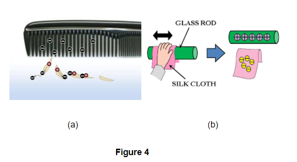
So, due to this concept of friction, the concept of charges came into notice. And further, coulomb was the one who gave more information about the charges.
Electric Charges
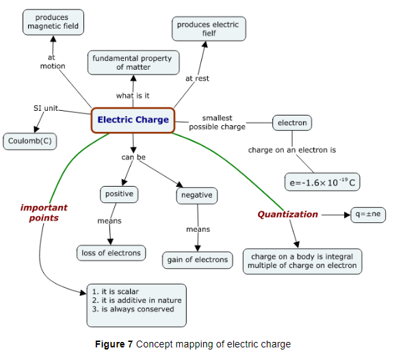
Electric charge is a fundamental property like mass; length etc. associated with elementary particles for example electron, proton and many more. The symbol used for it is (q) and the unit that is used to measure it is Coulomb which is denoted by C (unit). Electric charge is the property responsible for electric forces which act between the nucleus and electron to bind the atom together. Charges are of two kinds
1. negative charge
2. positive charge
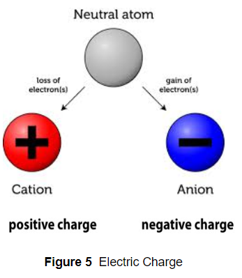
Electrons are negatively charged particles and protons, of which nucleus is made of, are positively charged particles. Actually nucleus is made of protons and neutrons but neutrons are uncharged particles. Electric force between two electrons is the same as electric force between two protons kept at same distance apart i.e., both set repel each other but the electric force between an electron and proton placed at same distance apart is not repulsive but attractive in nature.
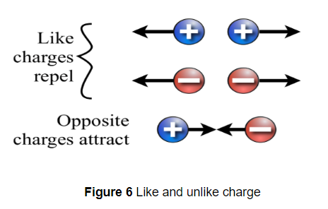
All free charges are integral multiples of a unit of charge e, where `e = -1.602 xx 10^(-19 )C` i. e., charge on an electron or proton. Thus charge `q` on a body is always denoted by
`q = n e`
where `n =` any integer positive or negative.
Unit of electric charge
Charge on a system can be measured by comparing it with the charge on a standard body. SI unit of charge is Coulomb written as C. 1 Coulomb is the charge flowing through the wire in 1 second if the electric current in it is 1A. Charge on the electron is `-1.602 xx 10^( -19 ) C` and the charge on the proton is positive of this value.
Types of substances depending upon their ability to conduct current
There is a category of materials in which electric charges can flow easily while in other materials charges cannot flow easily. We have different kinds of substances depending upon their power to conduct electricity. They are classified as:
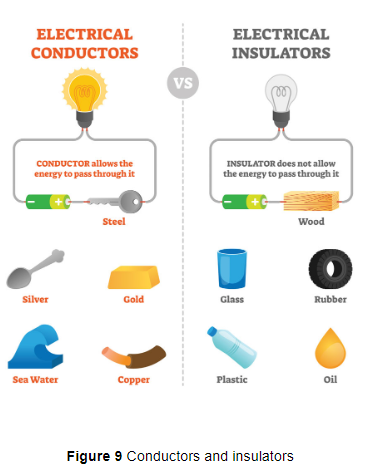
Conductors - Substances through which electric charges can flow easily are called conductors. Conductors have free electrons which are loosely held by nuclei of their atoms. They are those which allow current to pass through them.
For example- All metals like Cu, Al, etc are good conductors of electricity. Like in the given figure, the wire conducts electricity but the plastic insulation is an insulator.
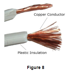
Insulators- Substances through which electric charges cannot flow are called insulators. insulators do not have free electrons as in insulators electrons are strongly held by nuclei of their atoms.They are those which do not allow current to pass through them.
For example glass rubber, mica, plastic, dry wood etc.
Presence or absence of free electrons in a material makes it a conductor or insulator. Those substances which give free electrons are good conductors and those which don’t have free electrons are poor conductors.
Electric current is the potential difference between the ends of the wire which makes the electric charges (or current) flow in the wire.
When two charged bodies at different electric potentials are connected by a metal wire, then electric charges will flow from the body at higher potential. to the one at lower potential (till they both acquire the same potential). This flow of charges in the metal wire constitutes an electric current.
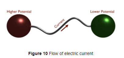
Figure 10 shows flow of electric current.
We now know that the electric charges whose flow in a metal wire constitutes electric current are the negative charges called electrons. Keeping this in mind, we can now define electric current as follows.
The electric current is a flow of electric charges (called electrons) in a conductor such as a metal wire. The magnitude electric current in a conductor is the amount of electric charge passing through a given point one second. If a charge of Q coulombs flows through a conductor in time t seconds, then of the magnitude I of the electric current flowing through it is given by :
Current, `I=Q/t`
The SI unit of electric current is ampere which is denoted by the letter A. We can use the above formula to obtain the definition of the unit of current called ampere. If we put charge Q = 1 coulomb and time t = 1 second in the above formula, then current `I` becomes 1 ampere. This gives us the following definition of ampere : When 1 coulomb of charge flows through any cross-section of a conductor in 1 second, the electric current flowing through it is said to be 1 ampere. That is,
`1 "ampere"= (1 "coulomb")/(1 "second")` or `1A=(1C)/(1s)`
Small Quantity of Electric Current: Small quantity of electric current is expressed in milliampere and microampere. Milliampere is written as mA and microampere as `muA`.
`1 mA` (milliampere) `=1/1000= 10^(-3 )A`
`1 muA` (microampere) `= 10^(-6 )A`
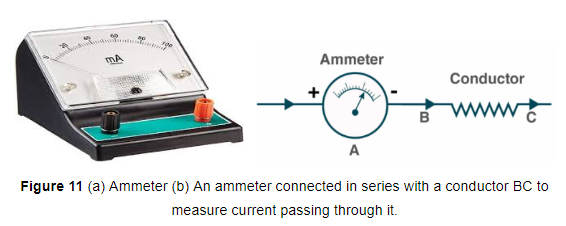
Ammeter - Current is measured by an instrument called ammeter. The ammeter is always connected in series with the circuit in which the current is to be measured (shown in fig. 11). For example, if we want to find out the current flowing through a conductor BC (such as a resistance wire), then we should connect the ammeter A in series with the conductor BC as shown entire current passes through the ammeter, therefore, an ammeter should have very low resistance so that it may not change the value of the current flowing in the circuit.
Continuous flow of electric current
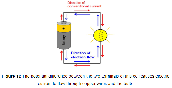
The simplest way to maintain a potential difference between the two ends of a conductor so as to get a continuous flow of current is to connect the conductor between the terminals of a cell or a battery. Due to the chemical reactions going on inside the cell or battery, a potential difference is maintained between its terminals. And this potential difference drives the current in a circuit in which the cell or battery is connected. For example, a single dry cell has a potential difference of 1.5 volts between its two terminals (+ terminal and - terminal). So, when a dry cell is connected to a torch bulb through copper connecting wires, then its potential difference causes the electric current to flow through the copper wires and the bulb, due to which the bulb lights up (see Figure 12). In order to maintain current in the external circuit, the cell has to expend the chemical energy which is stored in it. Please note that the torch bulb used in the circuit shown in Figure 12 is actually a kind of 'conductor'. We can also call it a resistor. It is clear from the above discussion that a common source of 'potential difference' or 'voltage' is a cell or a battery. It can make the current flow in a circuit.
Direction of Electric Current
When electricity was invented a long time back, it was known that there are two types of charges: positive charges and negative charges, but the electron had not been discovered at that time. So, electric current was considered to be a flow of positive charges and the direction of flow of the positive charges was taken to be the direction of electric current. Thus, the conventional direction of electric current is from the positive terminal of a cell (or battery) to the negative terminal, through the outer circuit. So, in our circuit diagrams, we put the arrows on the connecting wires pointing from the positive terminal of the cell towards the negative terminal of the cell, to show the direction of conventional current (see Figure above actual flow of electrons (which constitute the current) is, however, from negative terminal to positive terminal of a cell, which is opposite to the direction of conventional current.
How the Current Flows in a Wire
We know that electric current is a flow of electrons in a metal wire (or conductor) when a cell or battery is applied across its ends. A metal wire has plenty of free electrons in it.
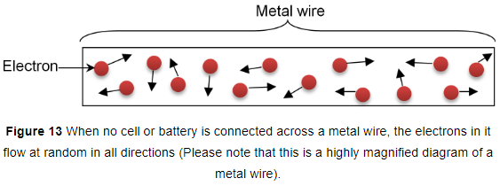
(i) When the metal wire has not been connected to a source of electricity like a cell or a battery, then the electrons present in it move at random in all the directions between the atoms of the metal wire as shown in fig. 13
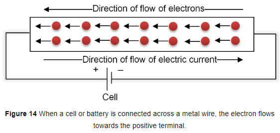
(ii) When a source of electricity like a cell battery is connected between the ends of the metal wire, then an electric force acts on the electrons present in the wire. Since the electrons are negatively charged, they start moving from the negative end to the positive end of the wire (see fig 14). This flow of electrons constitutes the electric current in the wire.
Electric Circuits
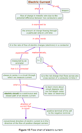
A cell (or battery) can make electrons move and electric current flow. But there must be a conducting path (like wires, bulb, etc.) between the two terminals of the cell through which electrons can move causing the electric current to flow. A continuous conducting path consisting of wires and other resistances (like electric bulb, etc.) and a switch, between the two terminals of a cell or a battery along which an electric current flows, is called a circuit. A simple electric circuit is shown in Figure 15.
Types of electric circuits:
1. Closed electric circuit
2. Open circuit
Open electric circuit : It is the circuit in which electric contact is broken at some point such that no current flows through the components of the circuit.
Closed electric circuit : The circuit in which all the components of a circuit are joined to one another such that a continuous current flows through them is a closed electric circuit. Some electronic devices with symbols used are:
Rheostat - It is defined as the variable resistance. It is connected to change the current in the circuit without changing the voltage source like cell etc.
Galvanometer - It is a device used to measure a very small amount of current as it has very low resistance.
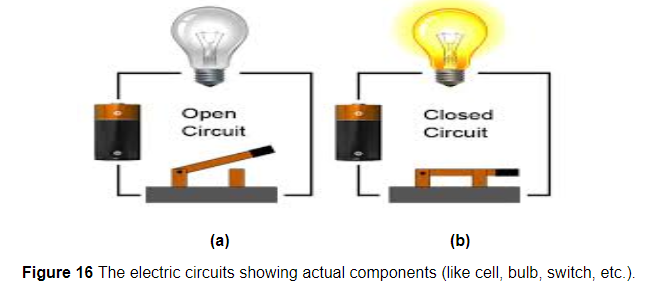
In Figure 16(a) we have a cell having a positive terminal (+) and a negative terminal (-). The positive terminal of the cell is connected to one end of the bulb holder with a copper wire (called connecting wire) through a switch. The negative terminal of the cell is connected to the other end of the bulb holder. If the switch is closed. So, the circuit in figure 16(b) is complete and hence a current flows in this circuit. This current makes the bulb light up.
If we open the switch, then a gap is created between the two ends of the connecting wire. Due to this, one terminal of the cell gets disconnected from the bulb and current stops flowing in the circuit. Thus, when the switch is open the circuit breaks and no current flows through the bulb, The bulb stops glowing.
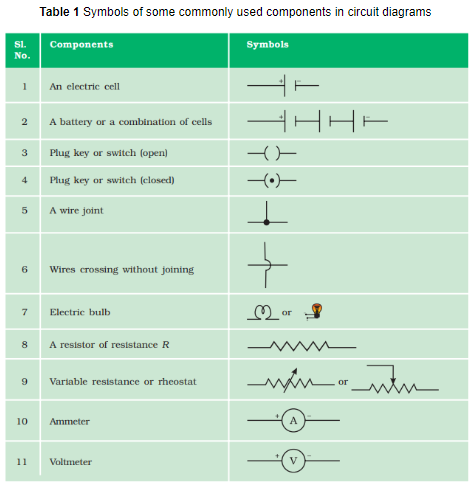
Symbols for Electrical Components (or Circuit Symbols)
In electric circuits, we have to show various electrical components such as a cell, a battery, connecting wires, wire joints, fixed resistance, variable resistance, ammeter, voltmeter, galvanometer, an open switch, a closed switch, and an electric bulb (or lamp), etc. Now, to draw the electric circuits by making the actual sketches of the various electrical components is a difficult job and takes a lot of time. So, the scientists have devised some symbols for electrical components which are easy to draw. They are called electrical symbols or circuit symbols. The common electrical symbols for electrical components which are used in drawing circuit diagrams are given below:
Charges present in a conductor do not flow from one end to another on their own. Electric charges or electrons move in a conductor only if there is a difference of electric pressure, called potential difference, along the conductor.
Electric Potential
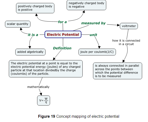
The electric potential (or potential) at a point in an electric field is defined as the work done in moving a unit positive charge from infinity to that point.
For example - When a small positive charge test is placed in the electric field due to another charge, it experiences a force. So, work has to be done on positive test charge to move it against this force of repulsion. So the work that we need to do in doing so is called electrostatic potential.
Potential is denoted by the symbol V and its unit is volt. A potential of 1 volt at a point means that 1 joule of work is done in moving 1 unit positive charge from infinity to that point. Since the unit of charge is coulomb, we can also say that: A potential of 1 volt at a point means that 1 joule of work is done in moving 1 coulomb of positive charge from infinity to that point. A more common term used in electricity is, however, potential difference.
Potential Difference
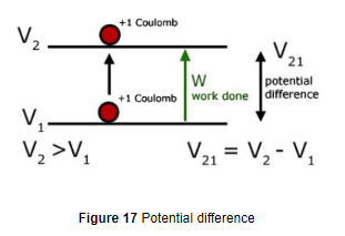
The difference in electric potential difference between two points is known as potential difference. The potential difference between two points in an electric circuit is defined as the amount of work done in moving a unit charge from one point to the other point.
When we need to move the charge between two specified points, then the work done in doing so is called the potential difference. So,
`"Potential Difference" = "work done"/"quantity of charge transferred" =W/Q` ……….(1)
The SI unit of electric potential difference is volt (V)
we can define 1 volt as : `1 "Volt"= 1 "joule"/1"Coulomb"`
So it is defined as: The Potential difference is said to be 1 volt when 1J of work is done in moving 1 C of charge from one point to another.
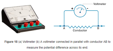
For example - This difference of potential may be produced by a battery, consisting of one or more electric cells. Potential difference across the terminals of the cell is generated due to chemical reaction within the cell. When the cell is connected to a conducting circuit element, the potential difference sets the charges inside the conductor in motion and produces an electric current. In order to maintain the current in a given electric circuit, the cell has to expend its chemical energy stored in it. The instrument that is used to measure its magnitude is called Voltmeter (shown in fig 18). There is an important feature that determines how we connect it. It is connected in parallel because it has a high resistance and also in parallel the potential difference remains constant.
The term volt gives rise to the word voltage which uses another name for Potential difference.
A current of 0.5 A is drawn by a filament of an electric bulb for 10 minutes. Find the amount of electric charge that flows through the circuit.
we have `Q = It`
`= 0.5 A xx 600 s`
`= 300 C`
How much work is done in moving a charge of 2 C across two points having a potential difference 12 V?
Thus, the amount of work W, done in moving the charge is
`W = VQ`
`= 12 V xx 2 C`
`= 24 J`
What is the difference between static and current electricity?
2. When objects are rubbed, a loss and/or gain of electrons occurs, which results in the phenomenon of static electricity.
3. Current electricity is normally controlled, and it is the more used phenomenon of electricity, in countless applications.
4. Static electricity is usually uncontrolled, and just happens occasionally or at irregular intervals.
5. Current electricity is generated by batteries and power plants.
1. A conductor carries a current of `0.2 A`. Find the amount of charge that will pass through the cross-section of the conductor in `30 s`. How many electrons will flow in this time interval if the charge on one electron is `1.6 xx 10^-19 C` ?
2. The filament of an electric lamp draws a current of `0.4 A` which lights for `3` hours. Calculate the amount of charge that flows through the circuit.
3. Calculate the number of electrons consituting one coulomb of charge.
Electrical circuits are represented by drawing circuit diagrams. A diagram which indicates how different components in a circuit have been connected by using the electrical symbols for the components, is called a circuit diagram. An electric circuit consisting of a cell, a bulb and a closed switch which was drawn in Figure 16(a) can be represented by drawing a circuit diagram shown in Figure 20(a). In the circuit diagram shown in Figure 20(a), a bulb has been connected to the two terminals of a cell by copper wires through a closed switch.
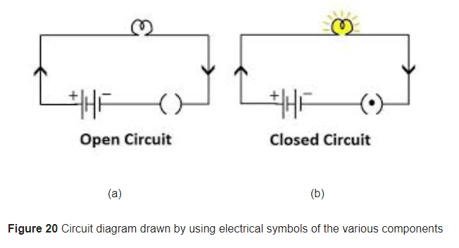
The electric circuit consisting of a cell, a bulb and an open switch which was drawn in Figure 16(b) can be represented by drawing a circuit diagram shown in Figure 20(b). In the circuit diagram shown in Figure 20(b), a bulb has been connected to the two terminals of the cell by copper wires through an open switch.
The circuit shown in Figure 20(a) is complete (due to closed switch). Since there is no gap, therefore, current flows in this circuit and the bulb lights up. In this case, the electrons can move through the external circuit. These moving electrons form an electric current. The circuit given in Figure 20(b) is broken (due to a gap because of an open switch), so no current flows in this circuit and the bulb goes off. The electrons cannot flow in this circuit due to the gap produced by an open switch.
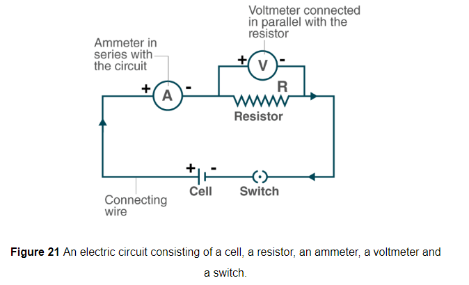
Another simple electric circuit has been shown in fig 21, in this circuit, a resistor R has been connected to the two terminals of the cell through a switch. An ammeter A has been put in series with the resistor R. This is to measure current in the circuit. A voltmeter V has been connected across the ends of the resistor R, that is, voltmeter is connected in parallel with the resistor. This voltmeter is to measure potential difference (or voltage) across the ends of the resistor R.
It is the generalization made by Georg simon ohm (in 1826) on the basis of the experiments he conducted. Ohm’s law gives a relationship between current and potential difference.
According to it, at a constant temperature, the current flowing through the circuit is directly proportional to the potential difference applied across the ends of the conductor. if `I` is the current flowing through the conductor and `V` is the potential difference (or voltage) across its end.
i.e. `V prop I`
Removing proportionately sign, we have
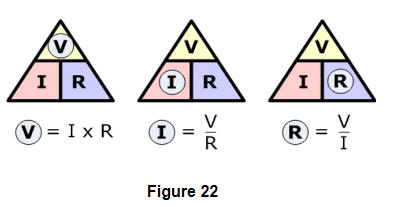
`V= R xx I`
Where R is constant for the given conductor at a given temperature and called resistance. Resistance is the property of conductors which resists the flow of electric current through it.
This means; potential difference V varies as electric current.
Or, `V/I=R`
Or, `I=V/R`
It is obvious from this relation that:
(i) the current is directly proportional to potential difference, and
(ii) the current is inversely proportional to resistance.
Since the current is directly proportional to the potential difference applied across the ends of a conductor, it means that if the potential difference across the ends of a conductor is doubled, the current flowing through it also gets doubled, and if the potential difference is halved, the current also gets halved. On the other hand, the current is inversely proportional to resistance. So, If the resistance is doubled, the current gets halved, and if the resistance is halved, the current gets doubled. Thus, the strength of an electric current in a given conductor depends on two factors :
(i) potential difference across the ends of the conductor, and
(ii) resistance of the conductor.
Resistance of a conductor
The electric current is a flow of electrons through a conductor. When the electrons move from one part of the conductor to the other part, they collide with other electrons and with the atoms and ions present in the body of the conductor. Due to these collisions, there is sum obstruction or opposition to the flow of electron current through the conductor. The property of a conductor due to which it opposes the flow of current through it is called resistance. The resistance of a conductor is numerically equal to the ratio of potential difference across its ends to the current flowing through it. That is :
Resistance= Potential difference/Current
or `R =V/I`
The resistance of a conductor depends on length, thickness, nature of material and temperature, of the conductor. A long wire (or conductor) has more resistance and a short wire has less resistance. Again, a thick wire has less resistance whereas a thin wire has more resistance. Rise in temperature of a wire (or conductor) increases its resistance.
The SI unit of resistance is ohm which is denoted by the symbol omega `Omega`.
We can define 1ohm as - resistance is said to be 1 ohm when 1volt of potential difference is applied which allows 1 ampere current to flow through it.
Graph Between V and I
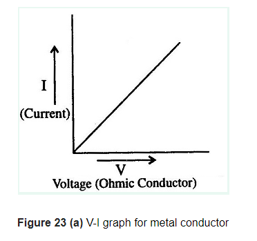
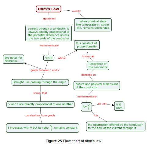
If a graph is drawn between the potential difference or voltage readings (V) and the corresponding current values (I), the graph is found to be a straight line passing through the origin (see Figure 21). A straight line graph can be obtained only if the two quantities are directly proportional to one another. Since the current- potential difference graph is a straight line, we conclude that current is directly proportional to the potential difference. It is clear from the graph that as the potential difference V increases, the current I also increases, but the ratio remains constant. This constant is called resistance of the conductor.
Resistance may be ohmic or non-ohmic.
(a) Resistors (or devices) for which potential difference and current graph is a straight line are called ohmic resistors (see Figure 23(a)). Their resistance remains same throughout their operation.
Examples are metallic conductors
(b) Resistors (or devices) for which potential difference-current graphs are not a straight line are called non-ohmic resistors.
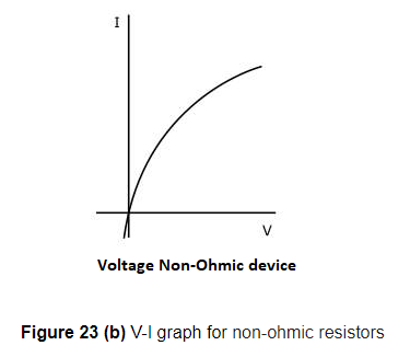
Examples are liquid electrolytes, diodes etc.
Verification of ohm's law: It can be verified as in this we connect the circuit as shown in the figure 24.
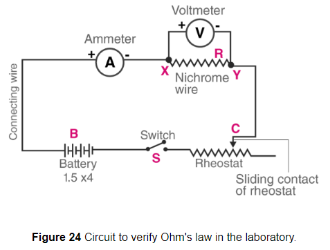
If we can show that for a given conductor, say a piece of resistance wire (such as a nichrome wire), the ratio potential difference/current is constant, then Ohm's law will get verified. Alternatively, we can draw a graph between the potential difference (V) and current (I), and if this graph is a straight line, even then Ohm's law gets verified. Let us see how this is done in the laboratory.
Suppose we have a piece of resistance wire R (which is the conductor here) (Figure 24), and we want to verify Ohm's law for it, that is, we want to show that the conductor R obeys Ohm's law. For this purpose we take a battery (B), a switch (S), a rheostat (Rh), an ammeter (A), a voltmeter (V) and some connecting wires. Using all these and the Connecting wires conductor R we make a circuit as shown in Figure 24.
To start the experiment, the circuit is completed by pressing the switch S. On pressing the switch, a current starts flowing in the whole circuit including the conductor R. This current is shown by the ammeter. The rheostat `R_h` is initially so adjusted that a small current passes through the circuit. The ammeter reading is now noted. This reading gives us the current I flowing through the conductor R. The voltmeter reading is also noted which will give the potential difference V across the ends of the conductor. This gives us the first set of V and I readings. The current in the circuit is now increased step by step, by changing the position of the sliding contact C of the rheostat. The current values and the corresponding potential difference values are noted in all the cases. The ratio potential difference/ current or V/I is calculated for all the readings. It is found that the ratio V/I has constant value for all the observations. Since the ratio of potential difference and current V/I is constant. Ohm's law gets verified because this shows that the current is directly V proportional to potential difference. The constant ratio V/I gives us the resistance R of the conductor. So, this Ohm's law experiment can also be used to determine the resistance of a conductor. If a graph is drawn between potential difference readings and corresponding current readings, we will get a straight line graph showing that current is directly proportional to potential difference. This also verifies Ohm's law.
1. Dependence of resistance on length of wire : Resistance is directly proportional to the length of the wire. More is the length of wire, more is the number of collisions and more is the resistance.
`R prop l`
2. Resistance on area of wire : Resistance is inversely proportional to the area of the wire. More is the area, less is the resistance as the number of collisions is less as they can pass easily.
`R prop 1/A`
3. Resistance on nature of wire: The electrical resistance of a conductor (say a wire) depends on the nature of which it is made. Some materials have low resistance whereas others have high resistance.
For example, if we take two similar wires, having equal lengths and diameters, of copper metal and nichrome alloy, we will find that the resistance of the nichrome wire is about 60 times more than that of the copper wire. This shows that the resistance of a conductor depends on the nature of the material of the conductor.
Conductors : have almost nil resistance
Semiconductors : have resistance
Insulators : have high resistance
4. Resistance on temperature : It has been found that the resistance of all pure metals increases on raising the temperature; and decreases on lowering the temperature. But the resistance of alloys like manganin, constantan and nichrome is almost unaffected by temperature.
Combining all factors we get :
`R= rho L/A`
Specific Resistance or Resistivity
Specific resistance or resistivity (e), of a conductor, is defined as the resistance of a conductor of unit length and unit area of cross-section.
From the factors affecting the resistance of a conductor, the resistivity is given by
`rho=R A/l`
Where ρ (rho) is the proportionality constant. It is called the electrical resistivity of the material of conductors. Specific resistance or resistivity is the characteristic property of the material of the conductor and depends only on the nature of the material and temperature.
In the above formula of resistance, if we consider it for wire of length 1m and area `1m^2` then resistivity is defined as the measure of resistance of wire 1m length and 1 meter square area .
`R= rho L/A`
From this equation,
`RA=ρl`
Or, `ρ=RA/l`
The SI unit of resistivity: Since, the SI unit of R is Ω, SI unit of Area is `m^2` and SI unit of length is m. Hence
Unit of resistivity `(ρ) =(Ω xx m^2)/m=Ωm`
Thus, SI unit of resistivity `(ρ)` is `Ω m`
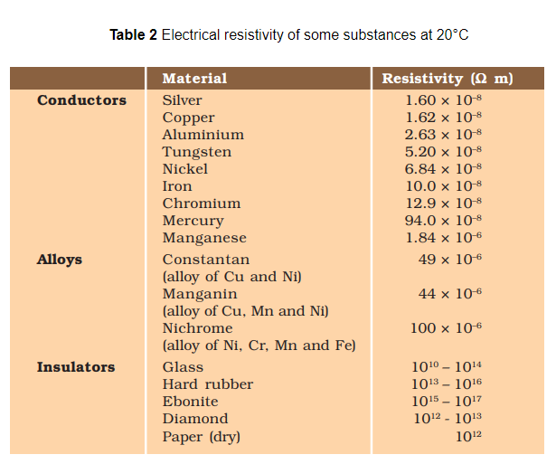
Materials having resistivity in the range of `10^(−8) Ω m` to `10^(−6) Ω m` are considered as very good conductors. Silver has resistivity equal to `1.60 xx 10^(−8) Ω m` and copper has resistivity equal to `1.62 xx 10^(−8) Ω m.`
Rubber and glass are very good insulators. They have resistivity in the order of `10^12 Ω m` to `10^17 Ω m.` Resistivity of materials varies with temperature.
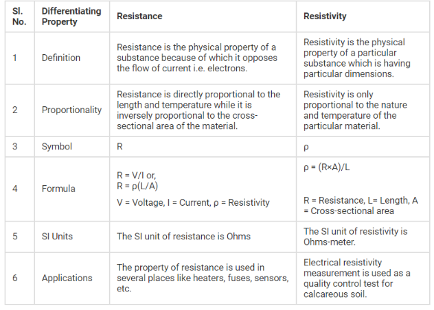
Difference Between Resistance and Resistivity
(a) How much current will an electric bulb draw from a 220 V source, if the resistance of the bulb filament is 1200 Ω? (b) How much current will an electric heater coil draw from a 220 V source, if the resistance of the heater coil is 100 Ω?
R = 1200 Ω.
we have the current
`I = (220 V)/(1200 Ω) = 0.18 A`
(b) We are given, V = 220 V, R = 100 Ω
we have the current
`I = (220 V)/(100 Ω) = 2.2 A`
Note the difference of current drawn by an electric bulb and electric heater from the same 220 V source!
The potential difference between the terminals of an electric heater is 60 V when it draws a current of 4 A from the source. What current will the heater draw if the potential difference is increased to 120 V?
current I = 4 A
According to Ohm’s law,
`R=V/I=(60 V)/(4A) = = 15 Ω`
When the potential difference is increased to 120 V the current is given by
current `=V/R= (120 V)/(15 Ω)=8A`
The current through the heater becomes 8 A.
Resistance of a metal wire of length 1 m is 26 Ω at 20°C. If the diameter of the wire is 0.3 mm, what will be the resistivity of the metal at that temperature? Using Table 2, predict the material of the wire.
the diameter d = 0.3 mm `= 3 xx 10^(-4) m`,
and the length l of the wire = 1 m.
Therefore, the resistivity of the given metallic wire is
`ρ = (RA/l) = (R(πd^2)/(4l))`
Substitution of values in this gives
`ρ = 1.84 xx 10^(–6) Ω m`
The resistivity of the metal at 20°C is `1.84 xx 10^(–6) Ω m`
From Table 2, we see that this is the resistivity of manganese.
A wire of given material having length l and area of cross-section A has a resistance of 4 Ω. What would be the resistance of another wire of the same material having length l/2 and area of cross-section 2A?
Now for second wire
`R_2= ρ (l/2)/(2A) =1/4 ρl/A`
`R_2= 1/4 R_1`
`R_2= 1Ω`
The resistance of the new wire is 1Ω
1. What is the resistance of an electric arc lamb when hot, if the lamp uses `20 A` when connected to a `200` volt line ?
2. Calculate the potential difference required across a conductor of resistance `5 Omega` resistance. It draws a current of `0.3 A` when glowing from a source of `3 V`. Calculate the resistance of the bulb when glowing and explain the reason for the difference in resistance.
3. How much current does an electric heater draw from a `220 V` line, If the resistance of the heater (when hot) is `50 Omega` ?
We know that current through a conductor depends upon its resistance and potential difference across its ends. In various electrical instruments, resistors are often used in various combinations and Ohm’s Law can be applied to combinations of resistors to find the equivalent resistance of the combination.
The resistances can be combined in two ways
1. In series
2. In parallel
To increase the resistance individual resistances are connected in series combination and to decrease the resistance individual resistances are connected in parallel combination.
Resistors in Series
When two or more resistances are connected end to end then they are said to be connected in series combination.
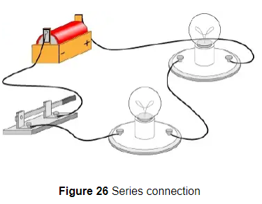
Figure below shows a circuit diagram where three resistors are connected in series combination.
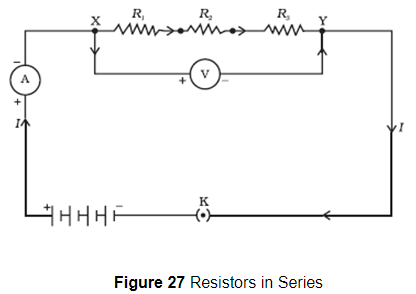
Now the value of current in the ammeter is the same irrespective of its position in the circuit. So we conclude that " For a series combination of resistors the current is same in every part of the circuit or same current flows through each resistor "
Again if we connect three voltmeters one across each resistor as shown below in the figure 26.The potential difference measured by voltmeter across each one of resistors `R_1 , R_2` and `R_3` is `V_1 , V_2` and `V_3 ` respectively and if we add all these potential differences then we get
`V= V_1+V_2+V_3` ………(1)
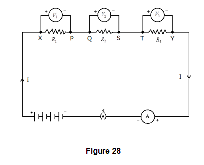
This total potential difference V in the above equation is measured to be equal to potential difference measured across points X and Y that is across all the three resistors in figure 27. So, we conclude that "the total potential difference across a combination of resistors in series is equal to the sum of potential differences across the individual resistors."
Again consider figure 28 where I is the current flowing through the circuit which is also the current through each resistor. If we replace three resistors joined in series by an equivalent single resistor of resistance R such that the potential difference V across it, and the current I through the circuit remains the same.
Now applying Ohm’s law to entire circuit we get
`V=IR` ……..(2)
On applying Ohm's law to the three resistors separately we have,
`V_1=IR_1` …….(3)
`V_2=IR_2` …….(4)
`V_3=IR_3` …….(4)
From equation 1
`IR=IR_1+IR_2+IR_3`..........(5)
Or, `R=R_1+R_2+R_3`.......(6)
So here from above equation 6 we conclude that when several resistances are connected in series combination, the equivalent resistance equals the sum of their individual resistances and is thus greater than any individual resistance.
Resistors in parallel
When two or more resistances are connected between the same two points they are said to be connected in parallel combination.
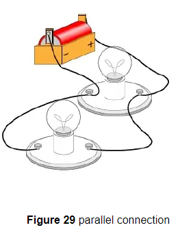
Figure below shows a circuit diagram where two resistors are connected in parallel combination.
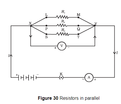
IMPORTANT NOTE
When a number of resistors are connected in parallel, then the potential difference across each resistance is equal to the voltage of the battery applied.
When a number of resistances are connected in parallel, then the sum of the currents flowing through all the resistances is equal to total current flowing in the circuit.
When numbers of resistances are connected in parallel then their combined resistance is less than the smallest individual resistance. This happens because the same current gets additional paths to flow resulting decrease in overall resistance of the circuit.
To calculate the equivalent resistance of the circuit shown in figure 30 consider a battery B which is connected across a parallel combination of resistors so as to maintain potential difference V across each resistor. Then total current in the circuit would be
`I=I_1+I_2+I_3`..........(7)
Since potential difference across each resistors is V. Therefore, on applying Ohm's Law
`V=I_1 R_1=I_2R_2=I_3R_3`
Or, `I_1=V/R_1,I_2=V/R_2, I_3=V/R_3`
Putting these values of current in equation 7 we have
`I=V/R_1+V/R_2+V/R_3`
`I=V(1/R_1+1/R_2+1/R_3)`
If R is the equivalent resistance of parallel combination of three resistors having resistances `R_1, R_2` and `R_3 ` then from Ohm's Law
`V=IR_(eq)`
or, `I=V/R_(eq)`.........(8)
Comparing equation (7) and (8) we get
`1/R_(eq)=(1/R_1+1/R_2+1/R_3)`
For resistors connected in parallel combination reciprocal of equivalent resistance is equal to the sum of reciprocal of individual resistances.
Value of equivalent resistances for capacitors connected in parallel combination is always less than the value of the smallest resistance in circuit.
An electric lamp, whose resistance is 20 Ω, and a conductor of 4 Ω resistance are connected to a 6 V battery (Fig.). Calculate (a) the total resistance of the circuit, (b) the current through the circuit, and (c) the potential difference across the electric lamp and conductor.
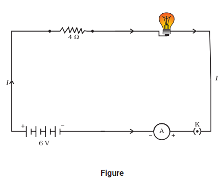
The resistance of the conductor connected in series, `R_2 = 4 Ω`
Then the total resistance in the circuit
`R =R_1 + R_2`
`R_s = 20 Ω + 4 Ω = 24 Ω`
The total potential difference across the two terminals of the battery V = 6 V.
Now by Ohm’s law, the current through the circuit is given by
`I = V/R_s`
`= (6 V)/(24 Ω)`
`= 0.25 A`
Applying Ohm’s law to the electric lamp and conductor separately, we get potential difference across the electric lamp,
`V_1 = 20 Ω × 0.25 A = 5 V`;
and, that across the conductor,
`V_2 = 4 Ω xx 0.25 A = 1 V`.
Suppose that we like to replace the series combination of electric lamp and conductor by a single and equivalent resistor. Its resistance must be such that a potential difference of 6 V across the battery terminals will cause a current of 0.25 A in the circuit. The resistance R of this equivalent resistor would be `R = V/I = (6 V)/ (0.25 A) = 24 Ω`
This is the total resistance of the series circuit; it is equal to the sum of the two resistances.
In the circuit diagram given in Fig., suppose the resistors `R_1, R_2` and `R_3` have the values `5 Ω, 10 Ω, 30 Ω` respectively, which have been connected to a battery of 12 V. Calculate (a) the current through each resistor, (b) the total current in the circuit, and (c) the total circuit resistance.
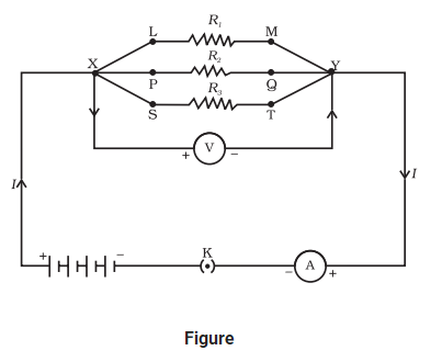
Potential difference across the battery, V = 12 V.
This is also the potential difference across each of the individual resistors; therefore, to calculate the current in the resistors, we use Ohm’s law.
The current `I_1`, through `R_1 = V/ R_1`
`I_1 = (12 V)/(5 Ω) = 2.4 A`
The current `I_2`, through `R_2 = V/ R_2`
`I_2 = (12 V)/(10 Ω) = 1.2 A`
The current `I_3`, through `R_3 = V/R_3`
`I_3 = (12 V)/(30 Ω) = 0.4 A`
The total current in the circuit,
`I = I_1 + I_2 + I_3`
= (2.4 + 1.2 + 0.4) A
= 4 A
The total resistance `R_p`, is given by
`1/R_p= 1/5 +1/10 +1/30= 1/3`
Thus, `R_p = 3 Ω`
In Fig., `R_1 = 10 Ω, R_2 = 40 Ω, R_3 = 30 Ω, R_4 = 20 Ω, R_5 = 60 Ω`, and a 12 V battery is connected to the arrangement. Calculate (a) the total resistance in the circuit, and (b) the total current flowing in the circuit.
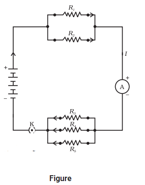
`1/ (R′) = 1/10 + 1/40 = 5/40`;
that is
`R′ = 8 Ω`
Similarly,
`1/ (R″) = 1/30 + 1/20 + 1/60 = 6/60`;
that is,
`R″ = 10 Ω`
Thus, the total resistance,
`R = R′ + R″ = 18 Ω`
To calculate the current, we use Ohm’s law, and get
`I = V/R = (12 V)/18 Ω = 0.67 A`
1. Three resistors are connected as shown in (Fig. 3.14) Through the resistor of `5 Omega`, a current of `1 A` is flowing.
(a) What is the potential difference across `AB` and across `AC` ?
What is the current through the other two resistors ?
(c) What is the total resistance ?
 .
.
2. A `24` volt battery is connected to the arrangement of resistances shown in (Fig.) Calculate
(i) the total effective resistance of the circuit,
(ii) the total current flowing in the circuit.
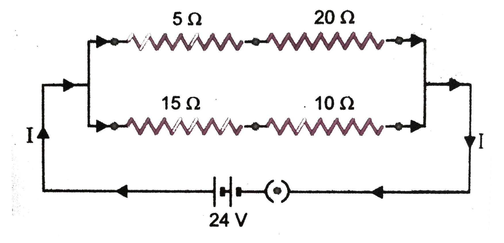 .
.
3. For the combination of resistors shown in (fig.)
(a) find the equivalent resistance between
(i) C and D and
(ii) A and B.
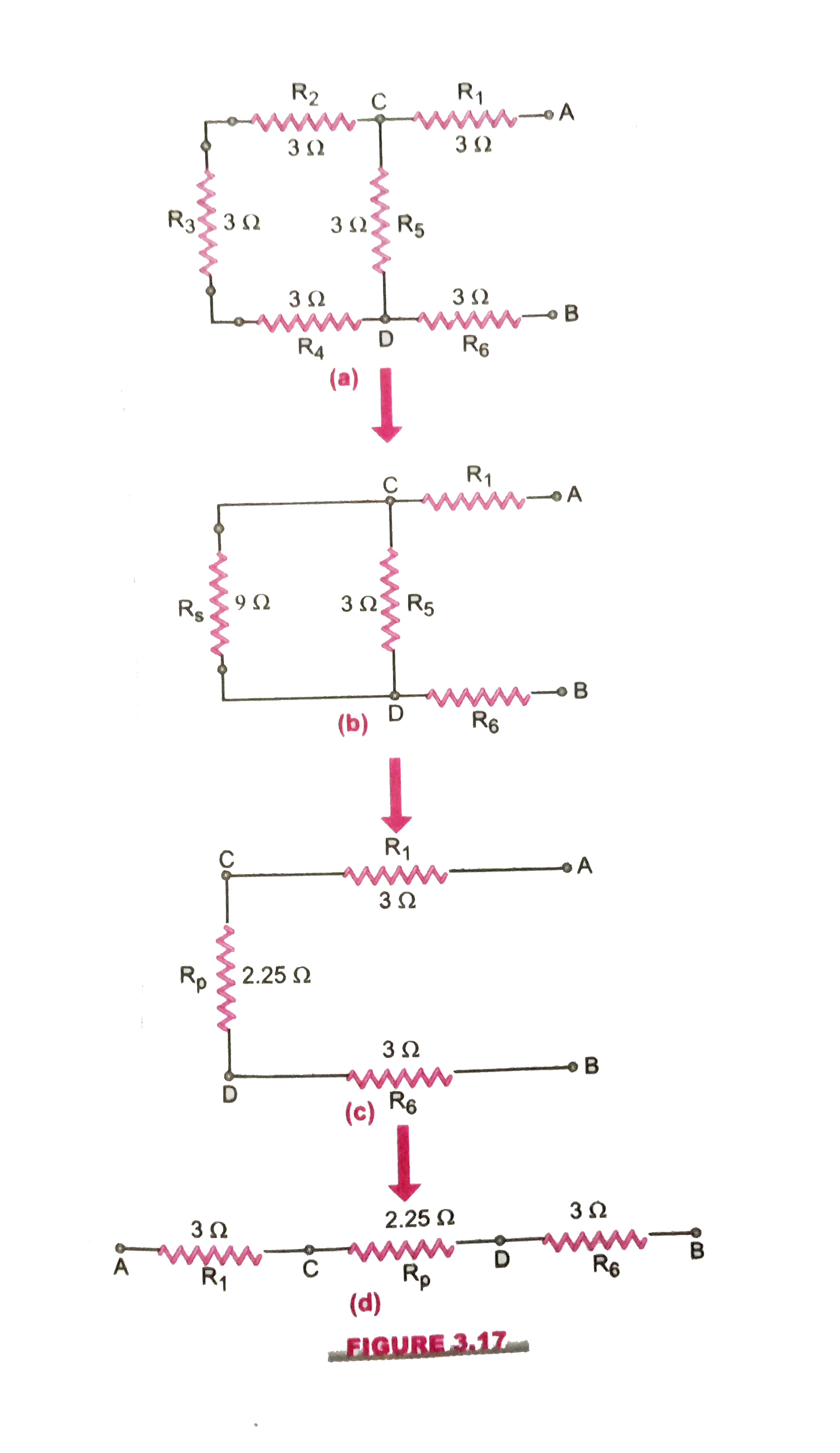 .
.
When electric current passes through a high resistance wire, the electrons move and when they move, they collide with each other. When they collide, heat is produced. This is called the heating effect of current. Heat produced depends upon the square of current, resistance and temperature.
This phenomenon occurs because electrical energy gets transformed into heat energy when current flows through a wire of some resistance, say R Ω. Role of resistance in electrical circuits is similar to the role of friction in mechanics. So we will now derive the expression of heat produced when electric current flows through a wire. So we will now derive the expression of heat produced when electric current flows through a wire.For this consider a current I flowing through a resistor of resistance R. Let V be the potential difference across it as shown in the figure 31.
Let t be the time during which charge Q flows. Now when charge Q moves against the potential difference V , then the amount of work is given by
`W=Q xx V`...........(1)
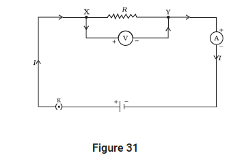
Figure 31
Therefore the source must supply energy equal to VQ in time t. Hence power input to the circuit by the source is
`P=VQ/t=VI`..........(2)
The energy supplied to the circuit by the source in time t is P×t that is, VIt. This is the amount of energy dissipated in the resistor as heat energy. Thus for a steady current I flowing in the circuit for time t , the heat produced is given by
`H=VIt`.........(3)
Applying Ohm's law to above equation we get
`H=I^2Rt` ………..(4)
This is known as Joule's Law of heating
According to Joule's Law of Heating , Heat produced in a resistor is
(a) Directly proportional to the square of current for a given resistor.
(b) Directly proportional to resistance of a given resistor.
(c) Directly proportional to time for which current flows through the resistor.
You know that nichrome wire is used in heating devices and the reason being
because
(i) It has high resistance
(ii) It does not burn even at high temperature
(iii) It has high coefficient of linear expansion
Applications of heating effect of current
1. The heating effect of current is utilized in the electrical heating appliances for example electric iron, room heaters, water heaters etc.
2. The heating effect of electric current is utilized in electric bulbs or electric lamps for producing light.
3. An electric fuse is an important application of the heating effect of current. The working principle of a fuse wire is based on the heating effect of current. When high current flows through the fuse (current higher than the rated value) then the heat developed in the wire melts it and breaks the circuit.
4. In an electric heater one type of coil is used. A high resistance material like nichrome or the same type of material is used as coil. The coil is wound in grooves on ceramic format or china clay. Flowing electric current through the coil it becomes heated. Due to high resistance the coil becomes red color forms.
We come across ‘power’ that is mentioned on all electrical appliances. So, if we define, it is the rate of doing work. Rate of doing work or the rate of consumption of energy is known as electric power
Mathematically,
`"Power" = "work done"/ "time taken"=W/t` ………..(1)
SI unit of power is Watt or Joule/sec which is denoted by letter W.
The power of 1 Watt is a rate of working of 1 Joule per second.
Actually Watt is a small unit, therefore , a bigger unit of electric power called Kilowatt is used for commercial purposes. Also ,
1 kilowatt = 1000 Watts
So, " the rate at which electric work is done or the rate at which electric energy is consumed is called electric power "
We will now derive a formula for the calculation of electric power.
we know that work done W by current I when it flows for time t under a potential difference V is given by `W = VxxI xxt` Joules ……….(2)
Putting this value of work done in equation 1 we get
`P=(V xxIxxt)/t=Vxx I`
or, `P=VI`.........(3)
Hence, Electric Power = voltage `xx` current
(a) Power in terms of I and R
From equation 3 we know that
`P=VI`
Now from Ohm's law
`V=IR`
Putting above equation in equation 3 we get
P=I×R×I
Power , `P=I^2×R`
Above formula is used to calculate power when only current and resistance are known to us.
(b) Power in terms of V and R
From equation 3 we know that P=VI Now from Ohm's law
`V=IR`
Or we have
`I=V/R`
Putting this value of I in equation 3 we get
`P=V×V/R`
`P=V^2/R`
This formula is used for calculating power when voltage V and resistance R is known to us.
It is clear from the above equation that power is inversely proportional to the resistance.
Thus the resistance of high power devices is smaller than the low power ones. For example , the resistance of a 100 Watt bulb (220 V) is smaller than that of 60 Watt (220 V) bulb.
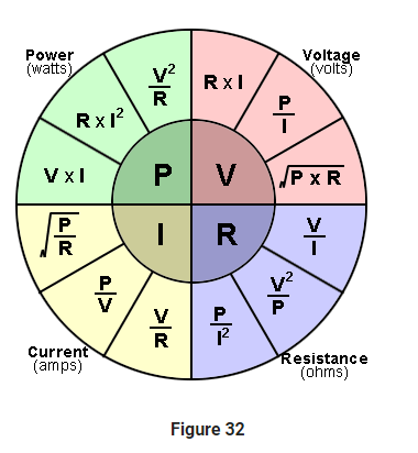
SI Unit of power : watt or Joule/sec
Bigger units : kilowatt=1000watt
megawatt=1000000 watt
gigawatt=1000000000watt
horsepower =746 watts
Electric fuse
It is a safety device that protects us from fire. It is shown in figure 33. It has two terminals `T_1` and `T_2` to which fuse wire is attached. The property of fuse wire is that it has very very low melting point. It is made up of an alloy consisting of lead and tin.
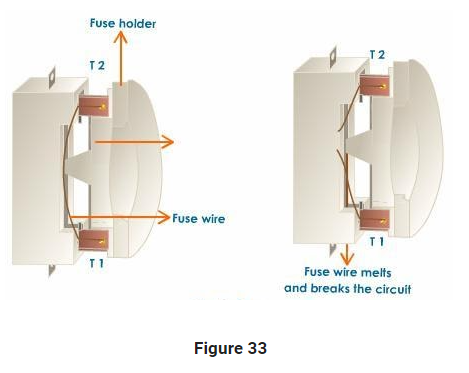
It works under two conditions:
Overloading : When many appliances are running together at the same time, they draw a large amount of current which produces a lot of heat that can even lead to fire.
Short circuiting : When live wire and neutral wire touch each other, the current exceeds the normal value and it can also cause fire.
In both the conditions, when current exceeds the normal value, excess heat is produced which melts the fuse wire and hence, fire is caused.
100 J of heat are produced each second in a 4 Ω resistance. Find the potential difference across the resistor.
We have the current through the resistor as
`I = sqrt(H/(Rt))`
`= sqrt[100 J/(4 Ω × 1 s)]`
= 5 A
Thus the potential difference across the resistor, V is
`V = IR`
`= 5 A × 4 Ω`
`= 20 V`
(a) An electric bulb is connected to a 220 V generator. The current is 0.50 A. What is the power of the bulb?
(b) An electric iron consumes energy at a rate of 840 W when heating is at the maximum rate and 360 W when the heating is at the minimum. The voltage is 220 V. What are the current and the resistance in each case?
`= 220 V xx 0.50 A`
= 110 J/s
= 110 W
(b) We know that the power input is `P = V I`
Thus the current `I = P/V`
(a) When heating is at the maximum rate,
`I = (840 W)/(220 V) = 3.82 A`;
and the resistance of the electric iron is
`R = V/I = (220 V)/(3.82 A) = 57.60 Ω`
(b) When heating is at the minimum rate,
`I = (360 W)/(220 V) = 1.64 A`;
and the resistance of the electric iron is
`R = V/I = (220 V)/(1.64 A) = 134.15 Ω`
An electric refrigerator rated 400 W operates 8 hour/day. What is the cost of the energy to operate it for 30 days at Rs 3.00 per kW h?
400 W × 8.0 hour/day × 30 days = 96000 W h = 96 kW h
Thus the cost of energy to operate the refrigerator for 30 days is
96 kW h × Rs 3.00 per kW h = Rs 288.00
1. Calculate the amount of work done to carry `4 C` of charge from a point at `100 V` to a point at `120 V`.
2. An electric bulb is rated at `200 V-100 W`. What is its resistance ? Five such bulbs burn for four hours. What is the electrical energy consumed ? Calculate the cost if the rate is `50` paise per unit.
3. Two coils of resistances `3 Omega and 6 Omega` are connected in series across a battery of `emf 12 V`. Find the electrical energy consumed in `1` minute in each resistance when these are connected in series.
1. A stream of electrons moving through a conductor constitutes an electric current. Conventionally, the direction of current is taken opposite to the direction of flow of electrons.
2. The SI unit of electric current is ampere.
3. To set the electrons in motion in an electric circuit, we use a cell or a battery. A cell generates a potential difference across its terminals. It is measured in volts (V).
4. Resistance is a property that resists the flow of electrons in a conductor. It controls the magnitude of the current. The SI unit of resistance is ohm (Ω).
5. Ohm’s law: The potential difference across the ends of a resistor is directly proportional to the current through it, provided its temperature remains the same.
6. The resistance of a conductor depends directly on its length, inversely on its area of cross-section, and also on the material of the conductor.
7. The equivalent resistance of several resistors in series is equal to the sum of their individual resistances.
8. A set of resistors connected in parallel has an equivalent resistance `R_p` given by `1/R_p= 1/R_1+1/R_2+1/R_3+.....`
9. The electrical energy dissipated in a resistor is given by `W = V xx I xx t`
10. The unit of power is watt (W). One watt of power is consumed when 1 A of current flows at a potential difference of 1 V.
11. The commercial unit of electrical energy is kilowatt hour (kWh). `1 kW h = 3,600,000 J = 3.6 xx 10^6 J`.
1. What does an electric circuit mean ?
2. Define the unit of current.
3. Calculate the number of electrons consituting one coulomb of charge.
4. Name a device that helps to maintain a potential difference across a conductor.
5. What is meant by saying that the potential difference between two points is `1 V` ?
6. How much energy is given to each coulomb of charge passing through a `6 V` battery ?
7. On what factors does the resistance of a conductor depend ?
8. Will current flow more easily through a thick wire or a thin wire of the same material when connected to the same source ? Why ?
9. Let the resistance of an electrical component remain constant while the potential difference across the two ends of the component decreases to half its former value. What change will occur in the current through it ?
10. Why are coils of electric toasters and electric irons made of an alloy rather than a pure metal ?
11. Use the data in Table 12.2 to answer the following -
(a) Which among iron and mercury is better conductor?
(b) Which material is the best conductor?
12. Draw a schematic diagram of a circuit consisting of a battery of three cells of `2 V` each, a 5 ohm resistor, an 8 ohm resistor, and a 12 ohm resistor, and a plug key, all connected in series.
13. Redraw the circuit of `Q.12`, putting in an ammeter to measure the current through the resistors and a voltmeter to measure the voltage across the `12 ohm` resistor. What would be the readings in the ammeter and the voltmeter ?
14. Judge the equivalent resistance when the following are connected in parallel.
(a) `1 Omega and 10^6 Omega`
(b) `1 Omega and 10^8 Omega and 10^6 Omega`.
15. An electric lamp of `100 Omega`, a toaster of resistance `50 Omega` and a water filter of resistance `500 Omega` are connected in parallel to a `220 V` source. What is the resistance of an electric iron connected to the same source that takes as much current as all three appliances and what is the current through it ?
16. What are the advantages of connecting electrical devices in parallel with the battery instead of connected them in series ?
17. How can three resistors of resistances `2 Omega,3 Omega`, and `6 Omega` be connected to give a total resistance of
(a) `4 Omega`
(b) `1 Omega` ?
18. What is : (a) the highest (b) the lowest total resistances that can be obtained by combinations of four coils of resistances `4 Omega,8 Omega,12 Omega,24 Omega` ?
19. Why does the cord of an electric heater not glow while the heating element does ?
20. Compute the heat generated while transferring `96000` coulombs of charge in one hour through a potential difference of `50 V`.
21. An electric iron of resistance `20 Omega` takes a current of `5 A`. Calculate the heat developed in `30 s`.
22. What determines the rate at which energy is delivered by a current ?
23. An electric motor takes `5 A` from a `220 V` line. Determine the power and energy consumed in `2 h`.
24. A piece of wire of resistance `R` is cut into five equal parts. These parts are then connected in parallel. If the equivalent resistance of this combination is `R'`, then the ratio `R//R'` is :
25. Which of the following terms does not represent electrical power in a circuit :
26. An electric bulb is rated `220 V and 100 W`. When it is operated on `110 V`, the power consumed will be :
27. Two conducting wires of the same material and of equal length and equal diameters are first connected in series and then in parallel in an electric circuit. The ratio of the heat produced in series and parallel combinations would be :
28. How is voltmeter connected in the circuit to measure potential difference between two points ?
29. A copper wire has a diameter of `0.5 mm` and a resistivity of `1.6 xx 10^-6 Omegacm`. How much of this wire would be required to make a `10 Omega` coil ? How much does the resistance change if the diameter is doubled ?
30. The value of current, `I`, flowing in a given resistor for the corresponding values of potential difference, `V`, across the resistor are given below :
`{:(I("ampere"),0.5,1.0,2.0,3.0,4.0),(V("volt"),1.6,3.4,6.7,10.2,13.2):}`
Plot a graph between V and I and calculate the resistance of the resistor.
31. When a `12 V` battery is connected across an unknown resistor, there is a current of `2.5 mA` in the circuit. Find the value of the resistance of the resistor.
32. A battery of `9 V` is connected in series with resistors of `0.2 Omega, 0.3 Omega, 0.4 Omega, 0.5 Omega and 12 Omega`. How much current would flow through the `12 Omega` resistor ?
33. How many `176 Omega` resistors (in parallel) are required to carry 5 A in 220 V line ?
34. Show how you would connect three resistors, each of resistance `6 Omega`, so that the combination has a resistance of
(i) `9 Omega`
(ii) `2 Omega`.
35. Several electric bulbs designed to be used on a `220 V` electric supply line, are rated `10 W`. How many lamps can be connected in parallel with each other across the two wires of `220 V` line if the maximum allowable current is `5 A` ?
36. A hot plate of an electric oven connected to a `220 V` lines has two resistance coils `A and B`, each of `24 Omega` resistance, which may be used separately, in series or in parallel. What are the currents in the three cases ?
37. Compare the power used in the `2 Omega` resistor in each of the following circuits :
(i) a `6V` battery in series with `1 Omega and 2 Omega` resistors, and
(ii) a `4 V` battery in parallel with `12 Omega and 2 Omega` resistors.
38. Two lamps, one rated `100 W` at `220 V`, and the other `60 W` at `220 V`, are connected in parallel to the electric mains supply. What current is drawn from the line if the supply voltage is `220 V` ?
39. Which uses more energy, a `250 W` TV set in `1 h` or a `1200 W` toaster in `10` minutes ?
40. An electric heater of resistance `8 Omega` draws `15 A` from the service mains for `2` hours. Calculate the rate at which heat is developed in the heater.
41. Explain the following :
(a) Why is tungsten used almost exclusively for filament of incandescent lamp ?
(b) Why are the conductors of electric heating devices, such as toaster and electric irons, made of an alloy rather than a pure metal ?
( c) Why is the series arrangement not used for domestic circuits ?
(d) How does the resistance of a wire vary with its cross-sectional area ?
(e ) Why are copper and aluminium wires usually employed for electricity transmission.
1. The work done in moving a unit charge across two points in an electric circuit is a measure of:
- current
- potential difference
- resistance
- power
Answer: B
2. The device used for measuring potential difference is known as:
- potentiometer
- ammeter
- galvanometer
- voltmeter
Answer: D
3. Which of the following units could be used to measure electric charge?
- ampere
- joule
- volt
- coulomb
Answer: D
4. Calculate the number of electrons consituting one coulomb of charge.
- `2.6 xx 10^(19)` electrons
- `6.2 xx 10^(19)` electrons
- `2.65 xx 10^(18)` electrons
- `6.25 xx 10^(18)` electrons
Answer: D
5. The outer name of potential difference is:
- ampereage
- wattage
- voltage
- potential energy
Answer: C
6. If the current through a flood lamp is 5A, what charge passes in 10 seconds?
- `0.5C`
- `2C`
- `5C`
- `50C`
Answer: D
7. OHM'S LAW
- current and resistance
- resistance and potential difference
- potential difference and electric charge
- current and potential difference
Answer: D
8. An electric bulb is rated `220 V and 100 W`. When it is operated on `110 V`, the power consumed will be :
- 100W
- 75W
- 50W
- 25W
Answer: D
9. Which of the following terms does not represent electrical power in a circuit :
- `I^(2)R`
- `IR^(2)`
- `VI`
- `(V^(2))/(R)`
Answer: B
10. Two conducting wires of the same material and of equal length and equal diameters are first connected in series and then in parallel in an electric circuit. The ratio of the heat produced in series and parallel combinations would be :
- `1:2`
- `2:1`
- `1:4`
- `4:1`
Answer: C
1. What is an electric circuit ? Distinguish between an open and a closed circuit.
2. If you were asked to think of electricity, many favourable and unfavourable images come to your mind.
(i) Name the favourable images.
(ii) What are the unfavourable images ?
(iii) What is common to all these images ?
3. What is the difference between a resistor and resistance ?
4. What do you mean by electric potential difference ? How is it measured ? Define its `SI` unit.
5. What is electrical resistivity ? How does it depend om temperature. Give its `SI` unit.
6. Derive an expression for electric energy in terms of potential difference, current and the time for which current flows through a conductor.
7. What do you understand by the rating of an electric appliance ?
8. What is Ohm's law ? How is it represented graphically ? Derive an expression for the resultant resistance of a series combination of resistors.
9. Discuss series and parallel combinations of resistors with their salient features.
10. Tap water conducts electricity whereas distilled water does not. Why ?
1. A soldering rod iron draws an energy of `45000 J` in `4` minutes when the current flowing through its element is `6 A`. Calculate the resistance of its heating element.
Answer: `5.2 Omega`
2. An electric bulb is marked `250 W - 200 V`. What information does it convey ? How many Joules of energy is consumed by this bulb in one hour ? How long will it take for the bulb to consume `1 kWh` ?
Answer: 900000 J, 4 h
3. An electric bulb is connected to a `220 V` generator. The current is `0.50 A`. What is the power of the bulb ?
Answer: 110 W
4. Two bulbs of `100 W` each and two coolers of `250 W` each, work on an average `6` hours a day. If the energy costs Rs. `1.75 per kWh`, calculate the monthly bill and the minimum fuse rating when power is supplied at `250 V`.
Answer: `Rs.220.50, 2.8 A`
5. An electric kettle is rated at `230 V, 1000 W`. What is the resistance of its element ? What maximum current can pass through its element ?
Answer: `52.9 Omega, 4.35 A`
6. A resistance of `10 Omega` is bent in the from of a closes circle. What is the effective resistance between the two at the ends of any diameter of this circle ?
Answer: `2.5 Omega`
7. Two resistors with resistances `10 Omega and 15 Omega` are to be connected to a battery of `emf 12 V` so as to obtain :
(i) minimum current
(ii) maximum current. How will you connect the resistances in each case ? Calculate the strength of the total current in the circuit in the two cases.
Answer: `2 A`
8. What is the safest voltage you can put across a `98 Omega-0.5 W` resistor ?
Answer: `7 A`
9. A torch bulbs is rated at `2.5 V and 750 mA`. Calculate its
(i) power
(ii) its resistance and
(iii) the energy consumed if the bulb is lighted for `4 hour`.
10. What does an electric circuit mean ?
2. The substance having infinitely high electrical resistance is called:
- conductor
- resistor
- superconductor
- insulator
Answer: D
3. Keeping the potential difference constant, the resistance of a circuit is doubled. The current will becomes:
- double
- half
- one-fourth
- four times
Answer: B
4. What happens to the resistance as the conductor is made thicket?
Answer: Resistance decreases
5. Why are copper and aluminium wires usually used for electricity transmission?
6. Why is nichrome used as a heating element ?
7. (a) What do you understand by the ''resistivity'' of a substance?
(b) A wire is 1.0m long, 0.2 mm in diameter and has a resistance of `10 Omega`. Calculate the resistivity of its material?
Answer: (b) `3.14 xx 10^(-7) Omega m`
8. How does the resistance of a conductor depend on:
(a) length of the conductor?
(b) area of cross-section of the conductor?
(c) temperature of the conductor?
9. The resistors, with resistances `5 Omega` and `10 Omega` respectively are to be connected to a battery of emf 6V so as to obtain:
(i) minimum current flowing (ii) maximum current flowing
(c) How will you connect the resistances in each case?
(b) Calculate the strength of the total current in the circuit in the two cases.
Answer: (a) For minimum current flowing: In series; For maximum current flowing: In parallel (b) 0.4A; 1.8 A
10. For a heater rated at 4kW and 220V, calculate:
(a) the current,
(b) the resistance of the heater,
(c) the energy consumed in 2 hours, and
(d) the cost if 1kWh is priced at Rs 4.60.
Answer: (a) `18.18 A` (b) `12.1 Omega` (c) 8 kWh (d) Rs 36.80